What Should You Do If Induction Heating Is Uneven?
Author
Date Published
Reading Time
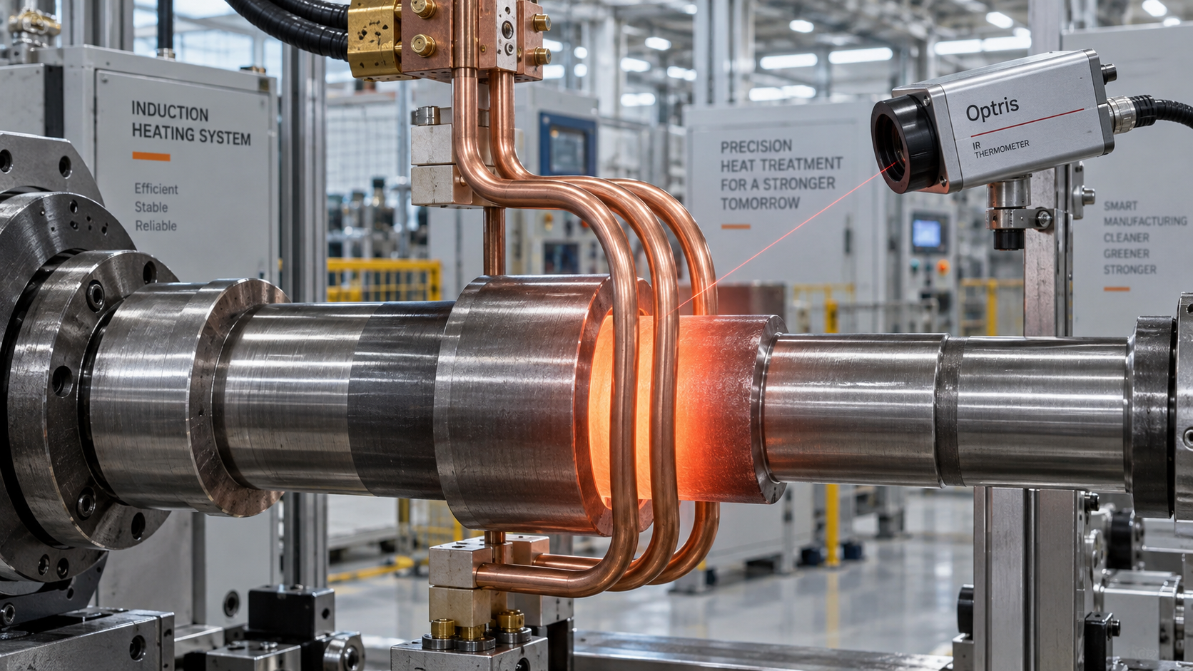
When one side of a shaft reaches temperature before the other, or a ring develops a hot band beside a cold section, increasing power is rarely the right first move. Uneven induction heating can cause inconsistent hardness, distortion, incomplete brazing, or local overheating. Start by verifying the temperature measurement, then check coil alignment, coil-to-workpiece spacing, material consistency, and the heating recipe.
If you are asking, “What should I do if induction heating is not uniform?” the practical answer is to identify where the variation occurs and whether it follows the part, the coil, or the process timing. That distinction determines whether you need to correct positioning, redistribute electromagnetic coupling, adjust frequency or dwell time, or investigate downstream cooling. Change one variable at a time and verify the result against the actual process requirement.
Is the temperature difference real, or is the measurement misleading?
Confirm the temperature pattern before modifying equipment. Infrared cameras and pyrometers can report different temperatures on surfaces that are equally hot but have different emissivity. Scale, oil, polished areas, changing oxidation, and reflected radiation can all distort readings. A bright machined surface beside an oxidized patch is especially easy to misinterpret.
Check the instrument’s wavelength range, emissivity setting, calibration status, viewing angle, and measurement spot size. The spot must fit inside the intended measurement area. On a moving workpiece, inconsistent triggering or measurement delay can also create an apparent temperature difference.
- Compare equivalent surface locations at the same point in the heating cycle.
- Record temperature during heating where practical, not only after power stops.
- Use a consistent, process-compatible surface condition for comparisons.
- Cross-check suspicious readings with an independently validated measurement method.
Thermocouples are not automatically a reliable reference inside an active induction field: electromagnetic interference and direct heating of the junction or leads can affect readings. Use instrumentation designed for the environment. Post-heating measurements can provide useful checks, but conduction may already have reduced the original hot-to-cold difference.
Define what “uniform” means for the operation. Surface hardening intentionally produces a temperature gradient through the section; brazing may require a controlled joint temperature rather than equal temperature throughout the assembly. Compare the measured pattern with the intended heating zone and acceptance limits.
What does the location of the hot spot tell you?
A temperature map becomes more useful when it is related to part orientation, coil position, and cycle timing. Record these together rather than saving an isolated thermal image.
In an approved diagnostic trial, changing a part’s angular orientation can help separate geometry-related heating from a fixed coil or fixture effect. A hot region that follows a distinctive part feature suggests a workpiece-related cause. A hot region that stays at the same machine-side position points toward alignment or field asymmetry. Do not rotate or reposition components during energization unless the machine is designed for that operation.
Which coil and positioning checks should come first?
Check mechanical repeatability before changing electrical settings. An otherwise suitable recipe cannot compensate reliably for changing coil-to-workpiece gaps. Inspect the loading stops, centering features, spindle runout, coil mounting, and any distortion of the coil itself.
Measure spacing around the intended heating zone, including shoulders and transitions. A smaller local gap often increases coupling, but the relationship depends on coil design and workpiece geometry. There is no universal gap dimension that guarantees uniform heating. Restore the validated geometry before experimenting with a different clearance.
Also inspect turn spacing and coil condition. A bent turn, damaged insulation, or an altered lead position can change the field distribution. Nearby metallic fixtures may absorb energy, distort the field, or draw heat away from the part. Review their material, location, and contact area.
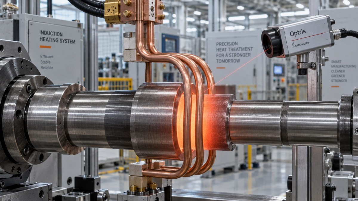
For cylindrical parts, controlled rotation can average circumferential differences when the process and handling system support it. Rotation does not resolve an axial cold zone or insufficient heating depth. For long components, scanning may improve coverage, but speed, overlap, and start-stop behavior must be coordinated with the coil’s heating footprint.
Persistent local overheating may require coil redesign or engineered flux concentrators to redistribute the field. These are application-specific changes: incorrect placement can intensify a hot spot or overheat the concentrator. Have the design reviewed rather than adding conductive shields or magnetic materials experimentally.
Should you change frequency, power, or heating time?
Choose the adjustment according to the observed failure. Frequency influences electromagnetic penetration; power and time govern the rate of energy input and the opportunity for heat to conduct through the part. They are related, but they are not interchangeable controls.
When the surface heats too quickly
Higher frequency generally produces shallower current penetration. If the surface approaches its temperature limit while the interior remains cold, a lower frequency may be appropriate for deeper heating. However, penetration also depends on electrical resistivity and magnetic permeability, both of which can change with temperature.
Ferromagnetic steels undergo a substantial permeability change near the Curie temperature. Coupling and heating behavior can therefore shift during the cycle. A setting that produces an acceptable initial ramp may not maintain the same distribution at higher temperature. Evaluate the full cycle rather than assuming a fixed penetration depth.
When a local hot spot limits the cycle
More total power usually makes the hottest region reach its limit sooner without correcting the underlying field imbalance. Address coil geometry and positioning first. Where the application allows, a slower ramp, staged power, or a controlled equalization period can reduce gradients by allowing conduction.
Longer cycles have limits. They can increase oxidation, broaden a hardened zone, or alter the required metallurgical outcome. Thin edges may still overheat even with a gentler ramp. Validate any revised recipe against maximum temperature, time at temperature, heating depth, and the finished-part requirements.
Frequency changes must remain within the generator, matching network, and coil system’s operating capability. Do not bypass protection functions or attempt tuning through exposed energized components.
Could the material or assembly be causing the variation?
Parts with the same external dimensions do not necessarily heat identically. Alloy composition, magnetic condition, previous heat treatment, wall thickness, and starting temperature affect the response. Compare affected parts with conforming parts using material records and dimensional checks, not appearance alone.
Holes, slots, sharp corners, and abrupt section changes alter current paths and heat flow. Thick sections may lag behind thin sections, while edges can develop concentrated heating. An assembly containing dissimilar metals introduces additional differences in coupling and thermal conductivity.
For brazing, inspect joint fit, contact conditions, filler placement, and fixture heat loss. A cold joint region may reflect heat being removed by a clamp or a heavy adjoining component rather than insufficient generator output. Increasing power can then overheat the more responsive member without bringing the entire joint into its required processing window.
Standardize incoming part temperature and surface preparation where those variables matter. A stable process may become inconsistent when warm parts from an upstream operation are mixed with parts stored at ambient temperature.
Why is hardness uneven when the heating pattern looks acceptable?
In induction hardening, temperature uniformity is only part of the diagnosis. Final hardness and case depth also depend on austenitization conditions, material hardenability, and quenching. An apparently acceptable surface temperature does not prove that the required subsurface transformation occurred.
Check quench delay, nozzle coverage, blocked outlets, flow stability, quenchant temperature, and concentration where applicable. Unequal cooling can produce hardness variation even when heating is repeatable. Conversely, uniform hardness at a few surface locations does not establish uniform case depth.
Use the inspection method specified for the component, such as hardness mapping and metallographic case-depth evaluation where required. Compare those results with the recorded heating and quench sequence. Avoid retuning the induction system solely to compensate for a cooling fault.
How do you test a correction without losing the process baseline?
Keep the original recipe and setup records before making adjustments. Use approved trial parts, and contain suspect production according to the site’s quality procedure when the variation could affect conformity.
- Record the baseline: part identification, starting condition, coil geometry, gap, frequency, power profile, heating time, motion, and cooling sequence.
- Choose one suspected cause: for example, inconsistent centering rather than changing centering, power, and dwell simultaneously.
- Repeat the trial: check whether the improvement persists across multiple parts and normal loading variation.
- Inspect the finished result: include the relevant dimensional, metallurgical, or joint-quality checks—not just peak temperature.
- Control the approved setup: document positioning limits, recipe settings, and inspection points so the correction survives changeovers.
For scanning systems, examine actual speed and power delivery through acceleration and deceleration regions. Average cycle time can look normal while local dwell varies enough to create overheating at the ends.
When does the problem require equipment-level investigation?
A sudden loss of uniformity after previously stable operation warrants checks for coil damage, loose connections, cooling problems, matching changes, and motion faults. Generator output alone does not establish how much energy is reaching each workpiece region. Compare available operating logs with the validated baseline.
Stop operation if there is arcing, coolant leakage near electrical components, abnormal coil heating, repeated protection trips, or suspected insulation damage. Electrical inspection and coil modification require qualified personnel following isolation, lockout, and manufacturer procedures; stored energy must also be addressed.
When alignment, material condition, and measurement have been verified but the same pattern remains, provide the equipment or coil specialist with the thermal map, part geometry, coil dimensions, operating recipe, and quality results. That evidence helps distinguish a correctable setup issue from a coil or frequency capability that cannot meet the required heating profile.
Expert Insights

Chief Security Architect
Dr. Thorne specializes in the intersection of structural engineering and digital resilience. He has advised three G7 governments on industrial infrastructure security.
Related Analysis
- Nov 01, 2026Choosing a Biosafety Cabinet for Microbiology: Class I, II, or III?Author :Dr. Aris Nano
- Oct 31, 2026Pallet Truck Scale Prices: What Affects the Cost of a Weighing Pallet Jack?Author :Dr. Aris Nano
- Oct 30, 2026How to Use a Concrete Test Hammer to Assess Concrete StrengthAuthor :Dr. Aris Nano
Recommended News
- Choosing a Biosafety Cabinet for Microbiology: Class I, II, or III?Author :Dr. Aris Nano

- Pallet Truck Scale Prices: What Affects the Cost of a Weighing Pallet Jack?Author :Dr. Aris Nano

- How to Use a Concrete Test Hammer to Assess Concrete StrengthAuthor :Dr. Aris Nano

- Metal Joining Services in Southeast Asia: How to Qualify SuppliersAuthor :Marcus Valve